The following article contains key information on properly creating junctions and the roadways between them. Be sure to review it in its entirety before editing the map.
Simple is better
When representing junctions, intersections, interchanges, cross roads, corners, etc., the Waze map does not need to perfectly match the road layouts it represents. The primary goal is to represent the real world as simply as possible in the maps and only introduce complexity in the maps to address complex issues.
The basics
This guide requires a complete understanding of editing the maps with Waze Map Editor (WME).
Map editing 101
Although it is highly recommended to read the Editing Manual before touching the map, it is required that you do not continue with this guide until you have read the following:
Junction definition


The Glossary on Junctions provides details on how junctions can appear differently in the editor depending on its state or condition.
A junction is made up of three things:
- Two or more road segments
- One point where all the segments meet (the junction point itself)
- Turns allowed or restricted when traveling from one segment to another through that junction point
Diverging roads

|

|
The simplest junctions often resemble a "T" and are considered diverging or branch roads. The branch road will normally meet the main road at nearly a 90 degree angle. This is the simplest situation to map, as the physical and logical views of the roads match up well. However when roads do not line up at right angles, there are issues to consider including navigation instructions and automatic map error generation.
Review the article on diverging roads for a complete understanding of the requirements and issues surrounding this junction type.
Crossing roads

|

|
The second simplest junction category is a "+" or "cross" four-way junction that intersects at 90 degrees. These roads are simple to map as the logical and physical views of the roads match up well. Like diverging roads, when they do not line up at right angles, there are issues to consider just like diverging roads.
Review the article on crossing roads for a complete understanding of the requirements and issues surrounding this junction type.
Controlling Turn Instructions
| Keep Right | Keep Left |
| Turn Right | Turn Left |
| Exit Right | Exit Left |
Turn instructions are critical for proper client navigation. They are controlled by:
- The angle set between segments at junctions.
- The road names.
- The road types.
Review the article controlling turn instructions for a complete understanding of the requirements and issues surrounding this topic.
Surface Streets
Y Intersections
When surface streets meet in a Y formation and we must carefully consider how they are mapped to provide useful navigation instructions. As the How Waze Determines turn/keep/exit maneuvers page explains, segment names and geometry are very important in determining what navigation instructions are given.
In the example below, the multi-lane surface street is known as Main Street to the west and Atlantic Ave to the east. The name change occurs when Main St branches off as a regular surface street.

The description above is how a human would probably describe the situation, but as you can see in the image above, a more technical description would be that Main St travels in a perfectly straight line and Atlantic Ave branches off of it. But if we map it that way in the editor, we create a major problem.

Since the multi-lane segment of Main St and the regular street segment of Main St have the same name, the routing engine automatically considers that to be "straight". If the two sections line up in a straight line the way they appear from the sky, then we are reinforcing the idea that "straight" is Main St. to Main St.
But as a typical driver would want, "straight" should be the path that remains on the multi-lane roadway, regardless of what the name is. To make sure the routing engine understands the proper treatment of the junction, we have to be deliberate with the segment geometry of all three involved segments. We end up with something like this:

Now the geometric definition of straight is the multi-lane portion of Main St. onto Atlantic Ave., since we have made that transition as close to zero degrees as possible. The regular street portion of Main St. now branches off at an angle close to 90 degrees. The routing engine should recognize that a turn is required. So the result is that Main St. to Atlantic Ave. has no announced turn, and multi-lane Main St. to surface road Main St. has a turn announced. Exactly what most drivers would expect in the real world.
No Outlet Roads
Roads which only have one way in and one way out can present challenges to the routing server, although they seem simple to our minds.
Dead Ends
Dead Ends (a.k.a. No Exit, Closed, No Through Road, No Outlet) are road segments that simply end, with no continuation or connections at one end. In some areas, a Dead End may be synonymous with a Cul-de-sac. In the US, a "No Outlet" sign may be used to indicate a road which itself is not a dead end, but it only connects to other dead end roads. It can also be used as a "friendlier" alternative to the typical Dead End sign.
Within the Map Editor it is possible to represent a dead end road with multiple segments if there are private driveways or parking lot roads mapped and connected. In that case, only the very last segment is considered the dead end segment.
Make sure that there is a junction indicator (the small blue dot, not just a geometry node) at the very end of the segment. While this one segment does not actually constitute a junction, the small blue dot is a visual indicator to the editor that the end of this segment is properly set up. This is necessary to ensure proper routing out of the segment. See the Cul-de-sac section below on when and how to fix this.

This final junction indicator must be located near the end of the road, but it should be located where there is still pavement as not to negatively impact client routes. Waze only considers the road fully traversed if both ends of the segment are fully crossed. If the junction indicator at the end of the segment happens to be at the edge of the pavement (or off of the road surface if aerials are not exactly aligned), it will be very difficult for a driver to cross that junction. A good rule of thumb is to have the end of the segment the same distance from the end of the pavement as it is from each side of the road.

With such a placement, the driver is given a chance to cross that junction indicator for that segment.
Cul-de-sacs
See also: Cul-de-sac article on Wikipedia
A Cul-de-sac (a.k.a. Court in the US) is a common treatment of a dead end street in a residential neighborhood.
In almost every situation, a cul-de-sac should be treated exactly as a dead end street, with the final junction indicator in the center of the bulb of the cul-de-sac. Be sure the free end of the final road segment has small blue dot displayed at the tip (when not editing or selecting the segment). If there is no blue dot, please correct it by following the steps for fixing dead ends.

The junction indicator should be located close to the middle of the bulb and NOT near the outer edges. If the end of the segment is positioned along the perimeter of the bulb, there may be difficulty in processing client routes. Waze only considers the road fully traversed if both ends of a segment are crossed. If the end of the segment happens to be on the curb (or off of the road surface if aerials are not exactly aligned), it will be very difficult for a driver to cross end end of the road segment. With the junction in the middle of the visual road, we give a driver a good chance to cross the end of the segment no matter where they drive within the bulb. The exception to this guidance is given in the next example.
The cul-de-sac below, with a small island, should be treated as a basic dead end with no loop. The island can be ignored, as there is no significant routing question for the driver once they get to the cul-de-sac.

As for placement of the final junction indicator, here we may get better results by moving the junction out from the true center and over to the outer perimeter of the central island. The shift ensures that the driver has a good opportunity to cross the end of the segment.

However, if the cul-de-sac has a very large bulb with a large island in the middle, it may better be treated as a Loop. A good rule of thumb is if you were standing at the end of the cul-de-sac, can you tell that it is just a cul-de-sac? Or does it look like two different roads? If you see an island, but are not sure if it is significant, leave the Loop out. If "Missing Road" errors occur on the road, then add a Loop.
Loops
Loops are roads that you can enter, and without reversing course, end up at the same place you started.
An important Map Editor rule is: a road segment must not start and end on the same junction node.
If this rule is not followed, the routing server will have difficulty in providing routes into and out of the loop. Any loop broken into two segments by a junction will not have this problem.
Hopefully there will be another roadway along the loop road which you can map, which will break the loop into two pieces. If there are no interruptions to the loop and the entire loop is represented by one road segment that connects with itself, we must insert a superfluous junction node along the loop segment. The specific location does not matter, but most people put it near the half-way point of the segment.


NOTE: It is very easy for an editor to find the extra junction node, assume it is truly superfluous, and delete it! This problem is magnified if the loop road is large or shaped so it is not obvious that it is a loop. One solution is to identify a path or driveway branching from the loop road and add it to the map, forcing a 3-way junction that would be less likely to be deleted.
NOTE: The Map Editor may be resistant in editing a loop that does not already follow the rule that it must be broken in two. If you run into saving errors, try one of the following approaches:
If the loop and the road leading to it have the same name:
- Select the loop and the road
- click the bridge icon that appears (one end of the loop will disconnect from the other)
- split the loop
- reconnect the disconnected end of the loop
- confirm turns
If the loop and the road leading to it have different names:
- draw a new road segment that connect to the loop/road junction
- give that new road the same exact name as the loop
- select the loop and the new road segment
- click the bridge icon that appears (one end of the loop will disconnect from the other)
- split the loop
- reconnect the disconnected end of the loop
- confirm turns
Here is a video on YouTube showing the second method.
Roundabouts and Traffic Circles

Please see the Roundabout page for a full discussion of this special type of junction.
At-grade connectors

With exceptions, don't set these segments as ramps! Watch out for all of the turns you need to restrict. For a full discussion, see at-grade connectors.
Bow tie intersections
The "bow tie" form of an intersection both simplifies and provides enhanced control when a dual carriageway road and a single carriageway road intersect.

By reducing the intersection to a single point, we gain control over U-turns and avoid short segments which may introduce complexity and routing issues.
The first instinct may be to map the intersection as the road is physically constructed -- using an "H" (a sideways H in this case) where each one-way roadway intersects the cross street. But if that method is used, there is no way to restrict the U-Turn movement from one one-way direction to the other since the center of the "H" carries both U-Turn traffic and traffic turning from the cross street. But mapped as a bow tie, there is a specific turn arrow that can allow or disallow the U-turn as needed.
Additionally, the center segment of the H may introduce complexity to the map. If the cross street changes names at the junction, care must be taken to make the center segment have no name assigned. This will cause the segment to inherit the appropriate name depending on the direction of travel. This center segment is then different from either side so future "select all segments" operations in the editor will not capture this segment which may complicate editing.
Finally, the Waze systems also have difficulty in capturing average speeds for short segments, especially when traffic does not travel across a majority of the segment which may happen in a wide intersection. The center of the H would be totally vertical in the example above, but turning traffic would be traveling in more of a 45 degree angle. Add in the inaccuracy of many consumer GPS chips and wide intersections and you may have traffic never actually driving over the segment for certain movements.
NOTE: Be aware of the geometry used in the bow tie. If the angles are too steep (45 degrees or greater) a driver traveling along one of the one-way segments may be told to "turn" or "stay" at the intersection instead of receiving no instruction.
NOTE: If the center of the physical "H" is long and/or allows traffic to stop and queue within the median of the divided roadway, a bow tie may not be appropriate. In these cases the segment may be long enough to justify being mapped especially if the one-way roads would have to deviate greatly from their physical location to meet in a single point.
Interchanges and ramps
An interchange is a road junction where two roads are connected by dedicated roadways, called ramps. The roads connected by an interchange do not intersect one another directly, and if they cross, the crossing is grade-separated.
When to use ramps
Use of the Ramp type is governed by the following rules:
Ramp and interchange style
For guidance on the proper configuration of ramps and interchanges, see Junction Style Guide/Interchanges.
Special Cases
Transitions
A transition is a non-junction depicted using a junction node.
Valid examples of where to use a Transition node include:
- Road name changes
- City Limits
- Road Direction changes
- Part of a Loop Road
An old reason to use a transition node was to indicate segments of the road with different house numbering. With the new point numbering scheme being adopted by Waze, this is no longer a reason to use transition nodes.
There may be existing Transition nodes on the map for other reasons (left after a connecting road was deleted, inherited from to the original base map import when things such as rivers and streams created junctions, etc.).
As long as we are certain it is not a valid Transition node, a superfluous junction node may be deleted. Doing so will simplify the map, eliminate turn restrictions to maintain, and reduce computing resource needs. Also consider removing the geometry node which will replace the junction node you delete, if that geometry node is not needed.
Roads to Nowhere
In certain situations it may be necessary to add road segments that are un-drivable in order to provide accurate navigation instructions.
Actual
A valid use of this technique is at the temporary end of a freeway. As a freeway is built, it is often opened in sections, up to a certain exit. If we map this as a regular freeway segment leading to a ramp segment, no announcement will be made for that final exit, no matter what we name the exit ramp.
This can be confusing if the ramp is set up as a properly signed and numbered exit, especially if a driver is traveling a long distance on this freeway. Imagine traveling down a freeway and seeing your next instruction is "turn left at Main St." You would probably wonder if there was a map error since you shouldn't be making left turns off of a freeways.
If we map even just a little of the future path of the freeway, this gives the routing engine a junction which will generate an "exit" instruction at the end of the freeway, thus eliminating any confusion.
Conversely, if we do NOT want an exit instruction at the end of a freeway, ensure there are no road segments extending past the final exit, to ensure the final exit is the only path out of the final freeway segment.
Fake
(coming soon)
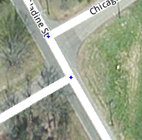
Offset Roads
Sometimes you will find two roads which cross, where one does not quite line up with the other.

There are a few things we need to look at in this situation.
- Do the roads actually line up in reality? If so we need to modify the junction to be a basic 4-way junction.
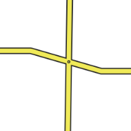
- Do the roads ALMOST line up in reality? If you were giving instructions to a person and would tell them to go straight with no mention of any slight turn or jog, then we want to make it into a 4-way junction. You may need to "split the difference" and not follow the centerline of either road to achieve this. The angles are exaggerated in this next example to show how the junction is forced to be close to 90 degrees, then we taper to the true centerlines of the roads. In practice this can be much more gradual and/or done while zoomed in very close.
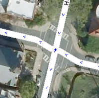
- Finally, is there a true separation between the roads? Would you need to say for example "turn left then make an immediate right"? If so then we will want to leave the junction such that the two sides do not align.
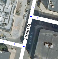
Since we want to avoid very short segments of road (the GPS chips in consumer devices can be very inaccurate which may make it seem that a driver skipped right over a short segment. This will result in automated map errors and possible route recalculations in the client,) it may be wise to shift the side roads as far apart from each other as possible with them still in the proper location (along the far curb lines for a residential street for example). This will maximize the length of the short segment between the side roads.