Falcon Map Snapper is a mechanism in Waze that positions the car on the user's map in relation to the mapped roads by collecting data like GPS, accelerometer, GPS speed, and more. It was implemented in 2021 to replace an old mechanism called The Matcher, which was a simpler mechanism that only used GPS position in relation to the mapped roads.
Overview 
What is The Matcher?
As you drive along your route, the arrow in the Waze app depicts your location on the Waze map. A technology, previously called the matcher, "snaps" the arrow to a segment on the map on your route. This association is very strongly bound to keep the arrow tied to the current route. As a result, Waze has often been slow to detect and recalculate changes when you deviate from the route, especially if the new route runs parallel to the old route.

What is Falcon Snapper?
The new Falcon Snapper is next generational and replaces The Matcher. It is smarter and more predictive than the previous matcher. It uses multiple sensors (including GPS) to determine the most likely position of the car in relation to the road. Its power setting is currently turned down though. Updates to our mapping standards have occurred, guiding editors in how to edit the Waze map to fully utilize the power of Falcon Snapper.
Falcon Snapper Mapping Principles
The community is leading the way in upgrading the Waze map to meet the new requirements of Falcon Snapper. We therefore need to change our thinking to these new principles:
- The map needs to be as accurate as possible and representative of reality: the position of the segment on the road, and the direction / angle of intersecting segments. Segments that do not meet these new principles could make Falcon hiccup, switch the arrow to another segment/route, and cause a poor user experience.
- We are moving away from using the map as a way to control the app. A map should be a map; it should be accurate and represent the world. The only time the map should deviate from reality is when an app function would be broken as a result of accurately drawing the map.
Mapping Guidance for Falcon Snapper
What are the primary goals for optimizing the map for Falcon Snapper?
Realign Segments
To enable Falcon to work as well as it can, segment positions need to be aligned with reality as closely as possible. To do this:
- Determine whether the satellite imagery in the area is trustworthy by comparing it with the GPS points layer.
- If the satellite imagery is trustworthy, align the segments to the center of the roadway using the satellite imagery.
- If the satellite imagery is not trustworthy, align the segments to the center of the tracks in the GPS points layer as closely as possible.
Determine Trustworthiness of Satellite Imagery
Determining the trustworthiness of satellite imagery is a very quick check you should do any time you’re adjusting roadway geometry. It takes only seconds (especially using the default shift-G and shift-R keyboard shortcuts to quickly switch on and off the GPS points and segments layers, respectively) and can save a ton of re-work.
First, enable the GPS points layer.
If the bulk of the arrows on the GPS points layer line up well with the roads on satellite imagery (even if there are some outliers), it is trustworthy, and you should use it as the basis for roadway alignment.
But if the arrows show a lot of traffic that is not aligned with roads visible in satellite imagery, you might have a problem.
Trustworthy Imagery


In cases where imagery is trustworthy, align segments with the satellite imagery.
Align the segments as close to the center of the road as practical.
- On roads with multiple lanes, the lane lines can be used as a guide for finding the center of the road.
- On one-way segments with an even number of lanes, the segment should cover the line between the middle two lanes.
- On one-way segments with an odd number of lanes, the segment should run dead center in the middle lane.
- Generally, follow the geometric center of the road.
- On two-way segments, the geometric center will not always be the same as the roadway centerline that splits the two directions of traffic.
- However, in cases where the geometric center of the roadway temporarily shifts near an intersection, don’t blindly “chase the turn lanes” if doing so would cause an abrupt correction at the intersection. Falcon Snapper is smart enough to know that roadways sometimes get wider near intersections. Keeping the path smooth is more important in these cases.
When the center of the road changes abruptly due to a change in the number of lanes, keep the transitions smooth.

One-way Segments Example 1 (Above Left) — Follow the geometric center of the roadway. On the 4-lane segments, the lane markings between the 2 middle lanes are a great reference.

One-way Segments Example 2
- Westbound, a transition from 3 lanes to 2 lanes & 1 lane—note the transition is smooth. For the 3-lane portion, follow the center of the middle lane. For the 2-lane portion, follow the lane markings between the two lanes.
- Eastbound upper, an easy 2 lanes, so follow the lane markings.
- Eastbound lower, a smooth transition from 1 lane & 1 lane into 2 lanes, then an exit on the right while the 2 lanes continue onward. For the 1-lane portions, follow the center of the roadway. For the 2-lane portion, follow the lane markings between the two lanes.


Don’t “Chase the Turn Lanes” — Falcon is smart enough to know that roadways sometimes get wider near a turn. “Chasing the turn lanes” leads to awkward geometry at the junction itself, which is a bigger problem.
It’s okay to realign segments even if they are only off by a few feet or half a lane. We want our segments to be as close to reality as possible so that Falcon can work as well as possible.
Non-Trustworthy Imagery
Imagery is not trustworthy if it is either misaligned or out of date.


In the first image, you can see a strong concentration of GPS tracks cutting through what appears to be forests and fields in satellite imagery. This strongly suggests that the roadway alignment has changed, so this imagery is not trustworthy.
In the second image, you can see a strong concentration of arrows that do not line up with the roadways visible on satellite imagery, but which have the same shape as the roadways.
If the imagery is not trustworthy, segments should be aligned with GPS tracks.
On a two-way road, you should see arrows of 2 different colors, showing 2 different directions of travel. Align the segment to the center of the two directions of travel:

On a one-way road, you should see a cluster of arrows of the same color. Align the segment with the center of this cluster.
Bridges and Overpasses
Even in areas with otherwise-trustworthy imagery, high-rise bridges and overpasses may be significantly misaligned. This is due to a phenomenon known as parallax. Because the satellite’s camera is not always directly above the places it’s photographing, anything not at ground level might not be aligned properly with things around it—while the satellite imagery provider does typically attempt to compensate for parallax error, it is not always successful. Where this error occurs, use satellite imagery to align segments at ground level, but follow the GPS tracks more closely as you near the peak of the bridge or overpass.

Though most of the GPS tracks in this image show that the imagery is trustworthy—even on most of the elevated ramps and freeways in this image, upwards of 100 feet above ground level—the selected reversible HOV lane segments are misaligned by a bit. While the satellite imagery provider does attempt to correct parallax errors, it’s not perfect (and the blurriness of the imagery on those elevated roadways is further evidence of this).

At the other end of the bridge, parallax error is quite evident on the elevated bridge approach segments, while the ground-level imagery is clearly trustworthy. Use the imagery at ground level; use the GPS tracks to align the bridge segments only.
Remove Fictional Doglegs and Micro-Doglegs
For years, doglegs and micro-doglegs have been used for several reasons: to force turn instructions (before turn instruction overrides were introduced), to force lane arrows (before lane arrow overrides were introduced), to make junction locations stand out on the map (before the on-route turn arrow overlay was introduced), and so on. All of these reasons have two things in common:
- they are no longer valid, as the map editor and app limitations that necessitated them have been addressed with native features, and
- they can cause problems with Falcon Snapper, which is sensitive to the angle of the driver’s movements.
Remember - The map needs to be as accurate as possible and representative of reality: the position of the segment on the road, and the direction and angle of intersecting segments.
Where found, micro-doglegs should be removed, and the segments mapped with the above guiding principles, to follow more closely with reality. Add Turn Instruction Overrides (TIOs) and Lane Angle Overrides (LAOs) where necessary to provide the best driver experience.


Exit, Fork, Split, Wayfinder, and AGC Geometry
Where two roads separate from each other as in an exit, fork, split, wayfinder, or AGC, there is one guiding question: is there a clear straight-ahead path? That is, does one outbound segment clearly continue the same path as the inbound segment?


- Left: no, there is no clear straight-ahead path.
- Center: yes, the I-610 E outbound path is the clear straight-ahead path—even though both paths run parallel (at first), I-610 E is the actual continuation and has more lanes.
- Right: yes, the left path is the clear straight-ahead path—even though these are exit ramps and there is no “continuation” per se, the left path is totally straight while the right path diverges immediately.
Where there is a clear straight-ahead path,
- The straight-ahead path should be more or less straight, with a smooth transition.
- The diverging path should be edited as follows:
- First, place the first geometry handle of the diverging segment
- on freeway exits and other ramps, at the nearest point to the exit from the following:
- If there's no solid white line, at the gore point (or “theoretical gore”, i.e., where the painted lines begin to diverge);
- If there's a solid white line, at its beginning;
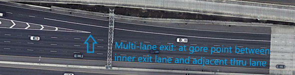
- On a multi-lane exit, at the gore point or (if present) solid white line between the inner exit lane and the main lanes of traffic;
- 1/4 mile before the gore point, on exits with a longer solid white line; or
- Halfway between the gore points of the exit and the previous exit.
- on at-grade connectors, at the gore point (or “theoretical gore”).
- on freeway exits and other ramps, at the nearest point to the exit from the following:
- Next, grab the node itself, where the segments meet, and adjust the geometry of the exit itself as follows:
- If the actual path of the exit diverges from the inbound path by less than 20°, adjust the node to create a 20° departure angle. This will allow for consistent timing of exit instructions and make it easier to report closures in the Waze client.
- If the actual path of the exit diverges immediately from the inbound path by more than 20°, adjust the node such that the exit path follows its true natural departure angle.
- Ensure that the last geometry handle before the node is at least 40 feet ahead of the node, and that the second geometry handle on the diverging path is at least 40 feet beyond the first geometry handle.
- First, place the first geometry handle of the diverging segment

Where there is not a clear straight-ahead path,
- Adjust the inbound segment geometry to follow the true path of the inbound segment,
- Set the first geometry handles of both outbound segments at the gore point, then
- Grab the node and adjust such that the angle between the outbound segments is at least 15°.
- If following the true natural departure angles leads to an inner angle of 15° or more, do that.
- If the outbound segments are both equally straight ahead, ensure that the outbound paths at the node are essentially symmetrical.


- Essentially symmetrical: yes, departure angles of outbound segments are very close (7° and 8°).
- At least 15°: yes (de-select any segments and select the node to check).
At the other end, ramps and AGCs should enter the flow of traffic smoothly and naturally. Place the final geometry handle of a ramp or AGC at the gore point as shown below, then grab the node and pull it along the road to create a smooth, natural entry angle:


Smooth re-entry. Just like the Apollo guys did back in the day.
Dividing Roads
As a “rule of thumb” - when there is a physical divider between the road (e.g. a small wall, grass, trees) and you cannot cross in a typical car, then map it with parallel one-way segments to more accurately represent reality.

When To Divide a Road
A road should be divided when any of the following conditions are met:
- It is an Interstate Highway, other freeway, or other controlled- or limited-access road with separated directions of travel, or
- There is a physical median or other traffic control device which makes it impossible or illegal to turn left onto or off of the road, including but not limited to where
- Houses, businesses, or other destinations are located directly on the street but are not accessible from the opposite direction of travel due to a median or other traffic control device that either physically or legally prohibits such access, or
- U-turns are required for proper navigation to or from side roads or destinations.
When Not To Divide a Road
A road should not be divided when any of the following conditions is met:
- There is a shared two-way center turn lane (of any width) between the directions of travel, or
- It is both possible and legal to make a left turn across the roadway centerline at any point along the road (e.g., across a normal double yellow line to enter a driveway).
This is expected to create a lot more H and # (hash) junctions. Where they’re complex, junction boxes may be required. See junction boxes below.
You must consider U-turn prevention and take measures to allow or disallow U-turns where possible or impossible. To prepare for turning off the old U-turn prevention, junction boxes should be used instead of prior guidance that will be deprecated.
Junction Boxes
With the creation of a lot more potentially complex junctions and accurately matching roads to reality, there may be a need to add junction boxes to the intersections, or sets of intersections, you’re creating.
A junction box should be used when necessary to:
- Prohibit an illegal or impossible path that cannot be prohibited with a simple turn restriction;
- Prevent illegal U-turns at H and # intersections;
- Enable collection of differential traffic data at # and H intersections (i.e., enable the routing server to tell the difference between left turn and straight-through delays);
- Enable collection of differential traffic data where traffic backs up past junction nodes before the intersection (e.g., because of another intersection, at-grade connector (AGC), exit ramp, or parking lot road) where the backup timing is expected to be different depending on which way the driver eventually exits the intersection; or
- To better collect traffic data on intricate intersections.
If a junction box is needed, make sure it is the last thing that needs to be done. Once added, the JB needs to be deleted for certain modifications to the segments and nodes beneath it (most notably, nodes under a JB cannot be moved, and segments connected to a JB cannot be cut).
In the United States, Level 4 and above can add/modify junction boxes. If you add one, please note on the Map Raid sheet. If you think one is needed, but you’re unable to add it, please note on the Map Raid sheet.
Mapping of Dedicated Turn Lanes / AGCs
Do dedicated turn lanes and at-grade connectors (AGCs) need mapping? In exceptional cases only.
In the below example, note the points A and B. Falcon Snapper has a feature called “curver” which expects drivers to turn in a curve between these two points. Curver stops at geometry handles, so be sure to minimize them close to intersections. Also note that the islands created by the AGCs are small and do not result in much of a delay in the final turn instruction.

An AGC is indicated if it:
- Red arrow: creates a large island, where, without the AGC the late turn instruction will result in the driver missing the turn.
- Green arrow: geo nodes are required close to the actual turn to shape the road to match reality that affect the Falcon Snapper curver ability.
- The AGC contains essential wayfinder information.

