| Line 140: | Line 140: | ||
: [[Image:Jct_cloverleaf_on_turns.png]] | : [[Image:Jct_cloverleaf_on_turns.png]] | ||
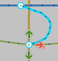
The connections to the Freeway segments may be treated in two ways | The connections to the Freeway segments may be treated in two ways: | ||
:[[Image:Jct_cloverleaf_options.png]] | |||
# (top) we can have the inner entrance and exit ramps have their own junction nodes with the Freeway. | |||
# (bottom) we can have the entrance and exit ramps share a single junction node with the Freeway. This allows us to eliminate the very short Freeway segment that may exist between the inner entrance and exit ramps.<br />It is best to offset this shared junction onto the Entrance ramp side of the surface street. This prevents the junction from accidentally being connected to the surface street or looking like it does. We favor the Entrance ramp side, because this would result in a slightly earlier exit instruction which is of course preferred over a late exit instruction. | |||
The determining factor of which design to use will partly depend on the actual size and scale of the specific interchange. | The determining factor of which design to use will partly depend on the actual size and scale of the specific interchange. | ||
Revision as of 22:11, 2 August 2012
Simple is better
When representing junctions (a.k.a. intersections, cross roads, corners, etc.) between roads, we sometimes have to blur the lines between the physical and logical worlds. The primary goal should be to represent things as simply as possible and only introduce complexity to deal with an issue.
The Basics ← START HERE
Lets start with the very basic case of one road branching off from another. Most of the time they will probably meet at close to a 90 degree angle. This is the simplest situation to deal with since the physical and logical views of the roads match up very well.

But you will probably find roads that meet at odd angles as well. Even in urban areas with rigid grids, you will often find at least one road that has existed since prior to the establishment of the grid which cuts through town at strange angles. The initial urge will be to represent the junction as it is in the physical world - two lines running into each other at some angle.

But there are issues with this method. Depending on the angles, the client may give a "Keep Right" instruction to the driver when a "Turn Right" instruction is more appropriate. In some cases, it is even possible the angle may be such that no instruction is given at all. Or worse yet, the routing engine may determine that it isn't possible to make a very sharp angle and not suggest a turn (in the example image, headed south and then turning left to head east).
To eliminate ambiguity, we need to treat the junction from a logical point of view. Since we want to be given basic "Turn Left" and "Turn Right" instructions, we have to treat it like it was a basic 90 degree intersection. But how do we do that when the roads don't actually diverge at 90 degrees? What we need to do is to add some geometry nodes to make the branch road leave the main road at close to 90 degrees, then we gradually curve to match the true departure angle.

Now we have a junction that logically works like a basic 90 degree junction but it also fits the reality of the physical world.
A ramp to a highway is another good example where additional geometry nodes are helpful. Especially since most ramps diverge at a very small angle from the road.

The drawback in this case (which also exists for the side road example above!) is that it may be very hard to see and click on the turn restriction arrows in the editor.
But if we just add one more geometry node to make the departure angle at the junction itself closer to 45 degrees...

...now the arrows are visible and accessible. Note that you can also press 's' in the editor to spread or separate the arrows at a junction if you still have difficulty clicking on an arrow. (see Editor Keyboard Shortcuts for more tips.)
We can easily scale the above approaches to a four-way junction. Again we can expect to mostly see angles close to 90 degrees.

And if we have that odd street cutting across town at an odd angle, we again want to avoid the odd angle at the junction...

...and we want to use geometry nodes to bring the actual junction to 90 degrees. You can zoom in as close as you can and add a single geometry node on each side. This will give us the proper angle but make it virtually invisible to users so it looks just like the physical world.

The above image is what you would see zoomed in as close as possible. Zoomed back out, it looks just like the image showing the junction without any geometry nodes.
Controlling Turn Instructions
Before going further, make sure you understand the mechanics of turn restrictions in the Map Editor. If turns are not properly enabled and restricted, you will never get the instructions you desire.
In the Basics section above, we touched on how to ensure a "Turn left/right" instruction would be given over a "Keep left/right" instruction.
Details of the mechanics behind this can be found on the How Waze determines turn / keep / exit maneuvers page, but here is a quick summary.
Geometry
Some of the complexity of the back-end algorithms can be avoided if we try to treat junctions with the logical view in mind as was done in the previous examples. If all junctions you edit follow just a few basic forms, it will be much easier to predict the behavior of an individual junction.
- Approximately 90 degree departure angle = Turn
- Less than 45 degree departure angle = Keep (or Exit for Ramps)
This knowledge allows us to control how a junction behaves by modifying a single geometry node in most cases. This is often useful for At-Grade Connectors where sometimes we prefer a "Keep right/left" and other times a "Turn right/left" would be more appropriate.
If we keep the departure angle less than 45 degrees, we would get a "Keep Right" to follow the curved one-way connector:

But if we move one geometry node to create a 90 degree angle, now we would receive a "Turn Right" instruction.

Segment Naming and Type
Besides the geometry of the road segments, the names and types of the segments come into play.
A basic rule of thumb is that if you want a turn to be announced, having a different name will improve the chances that will happen. For the At-Grade Connector example above, the connector should have a different name than the road it is leaving (See the How to name the connector section of the At-Grade Connectors page).
Roundabouts and Traffic Circles

Please see the Roundabout page for a full discussion of this special type of junction.
At-Grade Connectors
Make sure you don't confuse these segments for ramps! And watch out for turns you need to restrict. For a full discussion, see the At-Grade Connectors page.
Limited Access Interchanges
See also: Wikipedia article on Road Interchanges
When two roads meet in a limited access interchange (any situation where travel between grade separated roads is facilitated by ramps or slip roads alone), extra care must be taken.
If an exit ramp lines up with an entrance ramp, care must be taken to restrict the straight through direction to prevent "ramp-to-ramp routing" where the routing engine may try to take a shortcut from the Freeway, to the exit ramp, to the entrance ramp, and back to the Freeway instead of staying on the Freeway. That motion is inefficient and may be illegal in certain jurisdictions.
Care must be taken to not enable all turns in any situation where ramps meet unless all possible flows of traffic have been considered!
We also have to pay attention to the Level of the road segments since there will typically be many bridges and overpasses for any limited access interchange. If two roads cross without connecting, their levels must be different.
The following sections discuss some of the common Interchange designs. Note that some Interchanges may be a hybrid of these basic designs where one side or quadrant of the interchange may differ from the others.
Diamond Interchange

See also: Diamond Interchange article on Wikipedia
Common in wide open spaces where land acquisition and geography are not concerns, this Interchange design has ramps equally distributed across all 4 quadrants.
In the simplest form, this can be represented as single connections from the ramps to the surface street. Just be sure to restrict the straight through motion from the exit ramp onto the entrance ramp.

If the ramps connect to the surface street at multiple points, we have to avoid ramp-to-ramp routing as well as illegal turns which should use another ramp. First we see the turns that must be restricted for the exit ramps:


Then we see what must be restricted for the entrance ramps:

Note on Levels: The single surface street segment between the inner most ramps should be either raised or lowered in relation to the freeway segments depending on the actual geography at the interchange.
Cloverleaf Interchange

See also: Cloverleaf Interchange article on Wikipedia
In a Cloverleaf Interchange, left turns are eliminated from all movements between the Freeway and the surface street. First check the exit ramps.


Then check the entrance ramps for illegal turns.

The connections to the Freeway segments may be treated in two ways:

- (top) we can have the inner entrance and exit ramps have their own junction nodes with the Freeway.
- (bottom) we can have the entrance and exit ramps share a single junction node with the Freeway. This allows us to eliminate the very short Freeway segment that may exist between the inner entrance and exit ramps.
It is best to offset this shared junction onto the Entrance ramp side of the surface street. This prevents the junction from accidentally being connected to the surface street or looking like it does. We favor the Entrance ramp side, because this would result in a slightly earlier exit instruction which is of course preferred over a late exit instruction.
The determining factor of which design to use will partly depend on the actual size and scale of the specific interchange.
Note on Levels: The single surface street segment between the inner most ramps should be either raised or lowered in relation to the freeway segments depending on the actual geography at the interchange.
Folded Diamond

See also: Discussion of Folded Diamonds and A2/B2 Partial Cloverleafs on the Partial Cloverleaf Interchange article on Wikipedia
Geography or property ownership may prevent the ability for an interchange to be constructed with all ramps evenly distributed across the 4 quadrants of the interchange. When only two quadrants are used, it is typically called a Folded Diamond (basically a sub-type of a Partial Cloverleaf Interchange). The ramps may be all on one side (as in the examples in this section) or they may be located in diagonally opposed quadrants.
The unique situation presented by the Folded Diamond arrangement is having both Entrance and Exit ramps terminating on the same side of the surface street. Ideally both ramps should terminate on the same junction node to permit us to easily restrict the illegal and usually impossible ramp-to-ramp movement.
 '
'

Like with a basic Diamond Interchange, often it will be necessary to represent the ramps making multiple connections to the surface street. Restrict all non-permitted turns.


Note on Levels: Similar to a basic Diamond interchange, in most cases only the segment of the surface street that crosses the Freeway segments will need to be adjusted up or down.
Single Point Urban Interchange (SPUI)

See also: Single Point Urban Interchange article on Wikipedia
A SPUI is a very space and flow efficient design, but it takes extra attention to ensure the turns are correct. And as the name indicates, ideally there should be a single junction in the center. You may need to tweak the geometry of segments a bit off of alignment from the real physical world, but it should be minor if the interchange is a true SPUI.
The outer branches of the exit ramps are very much like in the case of a diamond interchange:

Where things get complicated is the inner branches leading to the Single Point. You need to avoid ramp-to-ramp in two directions and a reverse flow turn. Note: The ramp-to-ramp motion to facilitate a U-Turn (the top left arrow in the image below) may or may not be allowed depending on the specific interchange. Please validate this turn.

Luckily the entrance ramp restrictions are similar to the diamond interchange:

If you were to look at all the restricted turns at once, you may get the false impression that something is very wrong. But as you now know, a SPUI has almost as many restricted turns as allowed ones.

Note on Levels: The two surface street segments (between the outer ramps and connected to the Single Point) and the 4 ramp segments connected to the single point should all be the same level, either one higher or one lower than the level of the freeway segments above/below the single point.
Oddities
Offset Roads
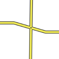
Sometimes you will find two roads which cross where one does not quite line up exactly from one side to the other.

There are a few things we need to look at in this situation.
- Do the roads actually line up in reality? If so we need to modify the junction to be a basic 4-way junction.
- Do the roads ALMOST line up in reality? If you were giving instructions to a person and would tell them to go straight with no mention of any slight turn or jog, then we want to make it into a 4-way junction. You may need to "split the difference" and not follow the centerline of either road to achieve this. The angles are exaggerated in this next example to show how the junction is forced to be close to 90 degrees, then we taper to the true centerlines of the roads. In practice this can be much more gradual and/or only done while zoomed in very close.
- Finally, is there a true separation between the roads? Would you need to say for example "turn left then make an immediate right"? If so then we will want to leave the junction such that the two sides do not align. Since we want to avoid very short segments of road, it may be wise to shift the side roads as far apart from each other as possible with them still in the proper location (along the far curb lines for a residential street for example). This will maximize the length of the short segment between the side roads.
