An interchange is a road junction where traffic can move between roads that do not intersect. The roads are connected by ramps, and if they cross, the crossing is grade-separated. They are most commonly used where one or more roads is a controlled-access highway. Complex interchanges may contain many highways and local roads meeting within small areas. Many different layouts have been developed by traffic engineers to optimize interchanges for size, complexity, traffic safety, navigation, and unimpeded traffic flow.
This article is a sub-article of the Junction Style Guide. As such, this article is a style guide as well. Representing interchanges on the map can be exacting and difficult. The guidance on this page will help editors to create accurate and usable map versions of these interchanges. The following sections discuss the proper style for ramps, interchanges, and some common interchange designs. Note that some interchanges may be a hybrid of these basic designs where one side or quadrant of the interchange may differ from the others. Also note that since interchanges often involve grade-separated crossings, the road elevation of the segments becomes important. If two roads cross without connecting directly, their elevations must be different.
Before reading through this article, be sure to fully understand the information in the Junction Style Guide.
Ramps
Ramps have a very specific purpose in Waze. They are intended to connect segments of minor highways, major highways, and freeways to roads where there are no at-grade crossings.
The Ramp type is used extensively in interchanges for three reasons.
- Ramp segment names are not displayed on the map.
- Ramp segments have essentially no penalty, so they can be used to connect freeways and major highways with each other without causing problems.
- Ramp segments are relatively thin but show at wide zoom levels, so interchanges do not distract from highways but can be seen at high speeds.
When to use ramps
Use of the Ramp type is governed by the following rules:
Geometry
Exits, forks, and wayfinders
This section concerns the geometry of the following junctions:
- exits, which are junctions at which one outbound segment (typically a ramp) carries traffic off of a road and the other outbound segment continues the same road as the entry segment;
- forks, which are junctions at which either both or neither outbound segment continues the same road as the entry segment; and
- wayfinders, a type of exit or fork which is set up to instruct the driver to stay on the road they're already on.
When mapping an exit or fork (or wayfinder), there is one guiding question: is there one clear straight-ahead path? That is, does one and only one outbound segment clearly continue the same path as the inbound segment?
-

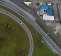
Yes, the left path is the clear straight-ahead path—even though these are exit ramps and there is no “continuation” per se, the left path is totally straight while the right path diverges immediately.
-
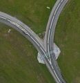
No, there is no clear straight-ahead path—both paths are equally straight ahead, so there is not one clear straight-ahead path.
-
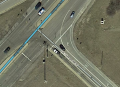
No, there is no clear straight-ahead path. This is a "typical" ramp fork.
-

No, there is no clear straight-ahead path—both paths are equally straight ahead, so there is not one clear straight-ahead path.


Where there is a clear straight ahead path
The straight ahead path should be more or less straight, with a smooth transition.
The diverging path should be configured as follows:
- First, place the first geometry handle of the diverging segment as follows:
- on freeway exits and other similarly-configured ramps, at the nearest point to the exit from the following:
- If there's no solid white line, at the gore point (or "theoretical gore", i.e., where the painted lines diverge)
- If there's a solid white line, at its beginning
- On a multi-lane exit, at the gore point or solid white line between the inner exit lane and the adjacent continuing lane
- 1/4 mile before the gore point, on exits with a longer solid white line
- Halfway between the gore points of the exit and the previous exit
- on at-grade connectors, at the gore point.

Use the natural departure angle for a segment with a true departure angle of at least 20°.
- on freeway exits and other similarly-configured ramps, at the nearest point to the exit from the following:
- Next, grab the node itself, where the segments meet, and adjust the geometry of the exit itself as follows:
- If the actual path of the exit diverges from the inbound path by less than 20°, adjust the node to create a 20° departure angle. This will allow for consistent timing of exit instructions and make it easier to report closures in the Waze client.
- If the actual path of the exit diverges immediately from the inbound path by more than 20°, adjust the node such that the exit path follows its true natural departure angle.
- Finally, ensure that the last geometry handle before the node is at least 40 feet ahead of the node, and that the second geometry handle on the diverging path is at least 40 feet beyond the first geometry handle.


Where there is not a clear straight ahead path

Whether both outbound paths are or neither outbound path is straight ahead:
- First, adjust the inbound segment geometry to follow the inbound segment's true path.
- Next, set the first geometry handles of both outbound segments in line with the gore point.
- Finally, grab the node and adjust such that the angle between the outbound segments is at least 15°:
- If following the true natural departure angles of the outbound segments leads to an inner angle of more than 15°, then do so.
- If the outbound segments are equally straight ahead, ensure that the outbound paths at the node are essentially symmetrical.
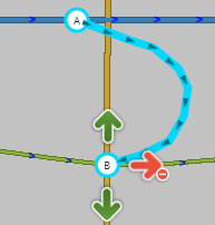
Re-entry
Where a ramp or AGC enters the flow of traffic, the driver's path should do so smoothly and naturally. Place the final geometry handle at the gore point or end of the solid white line, then grab the node and pull it along the road to create a smooth, natural entry angle.

Where an exit ramp ends at an intersection with a road, generally, map as you would any other intersection.
- If an exit ramp forks into distinct and separate paths, particularly on either side of a painted or physical island, create a fork with multiple outbound ramp segments.
- Where the ramp continues as a single roadway, and in some cases where a traffic island exists but is not particularly large or significant, a single ramp segment will suffice.
Generally, the same rules used to determine whether to map at-grade connectors can be used to determine whether to map a ramp island separately.
-

With a ramp island of significant size, use separate segments.
-
Map as you would any normal intersection.

.PNG)
Mapping considerations
Consider the following when editing interchanges and their component junctions.
Turn instructions
Where the inbound segment is a Freeway , Major Highway , or Minor Highway , if an instruction is given to a specific outbound segment,
- The default instruction to an outbound Ramp segment on the right will be "Exit right".
- The default instruction to an outbound Ramp segment on the left will be "Keep left."
- The default instruction to an outbound Freeway , Major Highway , or Minor Highway segment will be Keep left or Keep right.
As such, if a different instruction than the default is desired in any of these situations, use a turn instruction override.
Road names
Guidance for naming highway and ramp segments is found in the road names article.
Concurrent routes
If an exit carries a concurrent route away from the highway (e.g., a U.S. highway that was carried by an interstate up to the exit but splits off at the exit), that route designation should be added as an alternate name on all ramp segments that carry it. Note that this may affect the expected behavior of audible instructions, such that turn instruction overrides may be needed.
Using road name inheritance

In some situations, name inheritance should be used to provide optimal instructions. If a ramp is unnamed ("no name" box checked), the name of the next named road along the route will propagate backwards in navigation instructions. This is useful both for the sake of simplicity and for giving more specific instructions to traffic at exits with ramp forks. If an unnamed ramp is used at an exit and subsequent named ramps are used after the fork, drivers will see the name of whichever side of the fork they need to go to before they exit the highway. This method will provide more sufficient notification of an approaching decision point than a named exit ramp would, and it should be used as long as the names of both ramp forks are visible on signs at the start of the initial ramp. If an exit ramp has multiple lanes with a sign or part of a sign over each lane, using this method can even function as a form of lane guidance. If the example on the right from the MUTCD were mapped using name inheritance, the ramp exiting I-42 would not be named. The ramp that goes to I-17 southbound would be named "Exit 36: I-17 S / Portland" and the ramp that goes to I-17 northbound would be named "Exit 36: I-17 N / Miami." This would produce the following instructions:
- Traffic heading south on I-17 would receive
- at the exit: exit right to Exit 36: I-17 S / Portland
- at the fork: keep right to Exit 36: I-17 S / Portland
- Traffic heading north on I-17 would receive
- at the exit: exit right to Exit 36: I-17 N / Miami
- at the fork: keep left to Exit 36: I-17 N / Miami
Note that even though the exit number is by design not shown on signs at the ramp fork, it should be included in the names of the ramps for proper instructions at the exit. If signs at the ramp fork differ more significantly from signs at the exit, a different method of naming should be used.
Name inheritance, but signage on consecutive signs are different

If separate or split signs exist for traffic at an exit, but the signs at the ramp fork differ significantly from them, such as being further split or showing additional route numbers or control cities, the following method can be used:
- Leave the exit ramp unnamed
- At the ramp fork create a turn instruction override for no instruction going into a stub ramp segment of 19.69 ft (6 m)
- Name the stub according to the sign at the exit
- At the junction of the stub with the next ramp segment create a turn instruction override to match the expected instruction at the ramp fork, either keep left or right
- Name the next ramp segment according to the sign at the ramp fork or leave it unnamed to inherit farther ramp names
Because of name inheritance, the shortness of the stub, and the combination of turn instruction overrides, the name of the stub will be used in instructions at the exit, and the name of the ramp past the stub will be used at the ramp fork. This method should only be used when it's not possible to replicate what drivers see on guide signs using simple naming or name inheritance.
Wayfinders
A wayfinder is defined as any junction configured to instruct drivers to stay on the road they're already on. Wayfinders are generally used where, for one reason or another, the continuation of the highway is not obvious to drivers. For criteria and further details on mapping wayfinders, see wayfinder and turn instruction override.
Configurations
Diamond

See also: Diamond interchange article on Wikipedia
Common in wide open spaces where land acquisition and geography are not concerns, this interchange design has ramps equally distributed across all 4 quadrants.
In the simplest form, this can be represented as single connections from the ramps to the surface street.
The straight through motion from the exit ramp to the entrance ramp should typically be enabled, if legal to drive. Under normal circumstances, the big detour prevention mechanism discourages the routing server from routing someone off the freeway and directly back on. When the freeway path between the ramps is closed, or slow enough to overcome the Detour penalty, this off-on route may be given as a desirable alternative.
Be aware that the big detour prevention penalty is intended to discourage routing that leaves a freeway (or highway) and returns to the same freeway (or highway). Therefore, at least one name (primary or alternate) of the freeway/highway segment before the exit ramp must exactly match one name (primary or alternate) of the freeway/highway segment after the entrance ramp to trigger the penalty. For further information see the big detour prevention mechanism page.

If the ramps connect to the surface street at multiple points, restrict turns which should use another ramp. Review the section on ramp geometry and complexity for more details on this topic.
First we see the turns that must be restricted for the exit ramps:


Then we see what must be restricted for the entrance ramps:

Note on elevation: The single surface street segment between the inner most ramps should be either raised or lowered in relation to the freeway segments depending on the actual geography at the interchange.
Cloverleaf

See also: Cloverleaf Interchange article on Wikipedia
In a cloverleaf Interchange, left turns are eliminated from all movements between the freeway and the surface street. First check the exit ramps.


Then check the entrance ramps for illegal turns.

The connections to the freeway segments may be treated in two ways:

- (top) we can have the inner entrance and exit ramps have their own junction nodes with the freeway. Do not use this approach if there are collector/distributor lanes (or a similar situation) involved.
- (bottom) we can have the entrance and exit ramps share a single junction node with the freeway. This allows us to eliminate the very short freeway segment that may exist between the inner entrance and exit ramps.
It is best to offset this shared junction onto the entrance ramp side of the surface street. This prevents the junction from accidentally being connected to the surface street or looking like it does. We favor the entrance ramp side, because this would result in a slightly earlier exit instruction which is, of course, preferred over a late exit instruction. Use turn instruction overrides from the entrance ramp to give no instruction to the freeway and an exit instruction to the exit.
The determining factor of which design to use will partly depend on the actual size and scale of the specific interchange and if there is a collector/distributor involved.
Note on elevation: The single surface street segment between the inner most ramps should be either raised or lowered in relation to the freeway segments depending on the actual geography at the interchange.
Folded diamond

See also: Discussion of Folded Diamonds and A2/B2 Partial Cloverleafs on the Partial Cloverleaf Interchange article on Wikipedia
Geography or property ownership may prevent the ability for an interchange to be constructed with all ramps evenly distributed across the 4 quadrants of the interchange. When only two quadrants are used, it is typically called a folded diamond (basically a sub-type of a partial cloverleaf interchange). The ramps may be all on one side (as in the examples in this section) or they may be located in diagonally opposed quadrants.
The unique situation presented by the folded diamond arrangement is having both entrance and exit ramps terminating on the same side of the surface street. Ideally both ramps should terminate on the same junction node to permit easy restriction of the illegal and usually impossible ramp-to-ramp movement.
 '
'

Like with a basic diamond interchange, often it will be necessary to represent the ramps making multiple connections to the surface street. Be sure to read the Simple is better section in the Junction Style Guide.
Restrict all non-permitted turns.


Note on elevation: Similar to a basic diamond interchange, in most cases only the segment of the surface street that crosses the Freeway segments will need to be adjusted up or down.
Single-point urban interchange (SPUI)

See also: Single Point Urban Interchange article on Wikipedia
A SPUI is a very space and flow efficient design, but it takes extra attention to ensure the turns are correct. And as the name indicates, ideally there should be a single junction in the center. You may need to tweak the geometry of segments a bit off of alignment from the real physical world, but it should be minor if the interchange is a true SPUI.
The outer branches of the exit ramps are similar to a diamond interchange and ramp to ramp routing should be enabled if possible and legal. However, in many SPUIs such ramp to ramp routing is not possible:

Where things get complicated is the inner branches leading to the single point. You need to avoid ramp-to-ramp in two directions and a reverse flow turn. Note: The ramp-to-ramp motion to facilitate a U-turn (the top left arrow in the image below) may or may not be allowed depending on the specific interchange. Please validate this turn.

Luckily the entrance ramp restrictions are similar to the diamond interchange:

If you were to look at all the restricted turns at once, you may get the false impression that something is very wrong. But as you now know, a SPUI has almost as many restricted turns as allowed ones.

Note on Elevation: The two surface street segments (between the outer ramps and connected to the single point) and the four ramp segments connected to the single point should all be the same level, either one higher or one lower than the elevation of the freeway segments above/below the single point.
Collector/distributor lanes
These are lanes parallel to, but physically separated from, the lanes of a Freeway that serve to keep merging traffic out of the flow of through traffic on the mainline freeway.
Collector/distributor lanes serve as either:
- some of the ramps in an interchange, or
- local lanes in configurations with local-express lanes.
Collector/distributor interchange
Some interchange configurations make use of collector/distributor lanes to separate lower-speed merging traffic from high-speed through traffic. This is often used in cloverleaf interchanges and in groups of nearby exits.
Collector/distributor cloverleaf
This is a cloverleaf interchange that is connected to a collector/distributor instead of directly to the main roadway. Map collector-distributor cloverleaf ramps as you would any other ramp.

The detour prevention mechanism will discourage Waze from routing users onto the collector-distributor and back onto the freeway – as long as the street name on the freeway is the same before, throughout, and after the collector-distributor. Previously this feature was not available and the ramps were set up to restrict the through route. Some of these ramp configurations may still be set up that way, so they can now be configured as pictured above with the through route enabled.
Complex collector/distributor interchange

Where collector/distributor lanes are used as part of an interchange, use the Ramp type for the collector/distributor lanes. Name the ramp segments as you would any other ramp segment.
Ensure that a name on the Freeway segments is consistent before and after the collector/distributor lanes, so that the detour prevention mechanism will prevent Waze from routing users erroneously.
Local-express lanes

Local-express lanes are similar to collector/distributor interchange, but on a larger scale. While collector/distributor interchanges typically have an exit number or numbers, local-express lanes typically share the same name, differentiated by "Local" for the collector/distributor lanes and "Express" for the thru lanes.
A local-express lane configuration is not technically an "interchange"; however, since its physical characteristics are similar to those of a complex collector/distributor interchange, it is discussed here.
Where collector/distributor lanes are used as part of a local-express lane configuration,
- use the same type (most likely Freeway ) for the local lanes as is used for the express lanes, and
- name the road as it is signed: typically "[Name] Local [Direction]": for example, "I-96 Local W" for local lanes (and "I-96 Express W" for the corresponding express lanes).
Diverging diamond (DDI)
See also: Diverging Diamond Interchange article on Wikipedia.

Diverging diamond interchanges (DDI) are a type of diamond interchange in which the two directions of traffic cross one another on each side of a limited-access roadway. A DDI may pass over or under the limited-access roadway.
This type of interchange is unusual, in that it requires traffic to briefly drive on the opposite side of the road from what is customary for the jurisdiction. However, the design of the Diverging Diamond Interchange controls the driver's line of sight to ensure the cross-over action feels natural and goes unnoticed.
Segment directionality

All ramp and surface street segments are set as one-way. If you are creating a DDI along a road which is not divided, divide the road, first.
- For more details on how to properly divide/un-divide a road, see Best map editing practice § Dividing and un-dividing divided highways.
At-grade intersections
Junctions
As with all at-grade intersections in Waze, all DDI at-grade intersections are modeled with junction nodes, including the two signaled intersections where opposing directions of traffic "cross over" each other (inner surface road junctions). A DDI may also have two outer surface road junctions, where the one-way segments transition to two-way road segments.
Turn restrictions
Overview
There are four junctions in a DDI at which the turn restrictions must be checked - two inner surface road junctions where traffic crosses, and two outer surface road junctions where the road divides/joins on each side of the DDI.

Inner surface road junctions


Disable the two turns from one-way segments to the segments carrying traffic the opposite direction at both inner surface road intersections, for a total of four disabled turns.
Outer surface road junctions

Disable the single turn from the one-way segment carrying traffic exiting the DDI to the one-way segment carrying traffic entering the DDI at both outer surface road intersections, for a total of two disabled turns.
See also
Review the Wikipedia article on road Interchanges for further information on this topic.